Random-access memory (RAM)

It's better to have as much as possible.

Sony VAIO Laptop

Good performance.

Windows 7

Today the most common Operating System (OS).

Power switch on motherboard

Today it comes with almost every motherboard.

Graetz

AC to DC converter on board.

Pages

Sunday, January 7, 2018

Coil Counter

This is new/old project - Coil Counter
The idea of Coil Counter is to replace mechanical counting of turns with electronic device which will provide precise implementation of coil. Also I wanted to show that you can make diy, reliable&useful device with minimal costs, this device cost me around 20$. I have to mention that I just made electronic implementation while mechanical isn't finished yet.


How it works?
It works on quite simple way. First when you turn it on, you will see message Coil Counter then it will switch to menu Number of turns: now it's your turn to write how many turns you want via 3x4 matrix keyboard. Next, when you finished writing using navigation button # confirm your data. Next menu will ask you to write speed of motor in a way PWM: -30%+ ,  plus and minus are navigation buttons (- ==4, +==6) so with 4,6 buttons you can increase or decrease PWM by 5%. Also when you finished confirm it with #. The next menu is final it shows you all your written data (Nmbr of turns, PWM) So if you are satisfied confirm it with # or cancel it with *. It's possible to cancel data at any menu.

Maybe you wonder why PWM is set to 30%?
Well, I came to 30% empirically, testing motor speed at various PWM percentage. In that way 30% seemed just great to be initial value.

Take a look on Schematic.

Coil Counter Schematic


Assembly layer

Bottom Layer PCB

3D

3D

3D

As for sensors I used simple sensor with IR diode and photodiode aka. IR Sensor


Burned Speaker coil 
New Speaker coil


Wednesday, January 3, 2018

D-Class Amplifier THD, Output Power, Efficiency - TPA3116d2

After quite a while I have some time to make few posts on the blog. I'm starting with Amplifier

This is homemade D-Class Amplifier with IC TPA3116d2 (Texas Instrument). I made it for my new boombox but also to verify/confirm datasheet measurements/results. My interests were to check maximum Output Power, Total Harmonic Distortion (THD) and Efficiency. All results are shown below.
As for PCB design I used Altium Designer 17, whole design was made according to guides from official datasheet. PCB itself is 2 layer where polygon pours on both layers are used as heatsink
All components are 0805 size footprint, capacitors are X7R and LOW ESR, everything ordered from FARNELL.com all order codes are below as well.


List of equipment used:
  • ·         Oscilloscope – Siglent SDS1000L
  • ·         Function Generator – FeelTech FY2300A
  • ·         Bench power supply – Focus DC Power supply HY3005D-2
  • ·         Artificial Load  - 4Ohm/500W


Here is the internal schematic and Altium schematic


Altium Designer Schematic 

Bill of Material


N Designator Value Footprint Manufacturer Farnell
1 C16, C17, C18, C19 220nF/50V 0805 Kemet 1288261
2 C26,C27,C28,C29 680nF/50V 0805 Kemet 1414702
3 C20,C23,C30,C31,C32,C33 1nF/50V 0805 Kemet 1414660
4 C57,C34,C37,C38,C40 10nF/50V 0805 Kemet 1414662
5 C21,C24,C58 100nF/50V 0805 AVX 1740673
6 C11,C12,C13,C14,C15 1uF/50V 0805 Multicomp 1759502
7 C22,C25 220uF/35V 0805 Panasonic LOW ESR 1219473
8 U1 TPA31162 TSSOP-32 Texas Instruments 2144259
9 R10,R15,R16,R17,R18 3R3 0805 Multicomp 2447656
10 R13, R11, R14 100k 0805 Yageo 9237879
11 R12 20k 0805 Multicomp 2074395
12 L1,L2,L3,L4 10uH Bourns 2374152


Top Assembly Layer


Bottom Assembly Layer

Top Copper Layer

Bottom Copper Layer

3D Top 


3D Bottom


How it looks when printed out


Toner Density Spray 
Toner Density Spray is awesome for those who have old printers or printers with 600 DPI but also saves the thing if you don't want to print 2 pcs then glue it to fit perfectly.

Definitely RECOMMEND! Search in your store or on the internet. 

Price is around  15-20$


This is my illuminator with broken VTF125 bulb


Actual finished PCB


Measurement setup


 THD measurements were conducted under this conditions:
  • Supply Voltage U=12V
  • Sine wave frequency  f=1kHz
  • Input Signal Amplitude Uin=0.5V
  • Output Signal Amplitude Uout=1.5V
  • U1, U3, U5 is 1.st, 3.rd , 5.th Harmonic
FFT - Fast  Fourier Transformation


U(Supply Voltage)
Input signal Amplitude(sine f=1kHz)
Uout
U1
U3
U5
12V
0.50V
1.5V
580mVrms
6.3mVrms
3.3mVrms


According to datasheet difference in THD is 22% .


Output Power, Efficiency is shown below:

Supply Voltage(U)
Supply Current(I)
Uin(sine, f=1kHz)
Rt (Load)
Up-p
Uout(peak-peak
P

Pout
h
12V
1.46A
1.3V
4Ω
10.6V
17.52W
14.04W
80.16%


According to datasheet 15W I measured in real environment 14.04W which is 0.96W or 6.8% less than manufacturer said. Which is quite good

You probably noticed the difference between Pout and P (all power) that's because of dissipated power which converts to heat on components with real impedance (parasitic resistance).
Dissipated power in my measurement can be calculated in 2 ways:


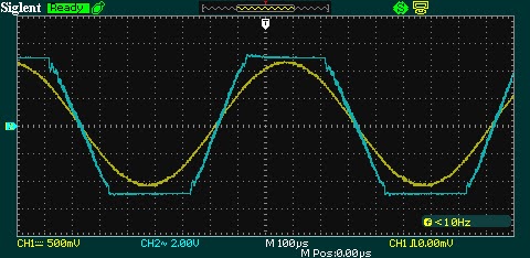
While I was doing my measurements I've also noticed that there are no maximum Amplitude of  Input Signal in datasheet so I measured that as well.
Maximum Amplitude is a bit smaller than we can see Clipped signal on Oscilloscope

As we can see firstly there is cutting on the negative half-periode than positive half. That's happening due to low bias voltage.

Input Signal Amplitude
Clipping voltage
Half periode
1.3V
4.4V
Negative
1.5V
5.2V
Positive


First cutting negative half

Cutting positive and negative

Total cut off


To summarize we can see that there are some deviations from official datasheet due to lack of mathematical analytic formulas we can't confirm our measurements nor design amplifier to meet our special requirements. That's not reason that this amplifier is not good enough to use for your boombox, speaker box, bluetooth, bigger audio systems (2.1) etc. on the contrary is Perfect due to price and easy to use.


Saturday, February 6, 2016

***New Project*** First Portable PCB Saw Table

After some time creating and cutting my PCBs with hand saw I decided to stop practice that and make something more suitable for 21.st century and that is Portable MINI PCB SAW Table. Also, as all my Project are on budget the same is with this one. I made it with minimal costs, Motor was from my old electric driller, table was found in garbage only thing I had to buy and give to processing was bottom aluminum plate, motor holder and saw blade. PWM controller left from another project, case as well. So overall price is <50$


Parts:
  • 1-Electric driller with battery (18V)
  • 1-Old saw table 
  • 1-PWM controller (from ebay)
  • 1-Saw blade
  • 1-Enclosure for controller
  • 1-Green LED
  • 1-1k Resistor
  • 1-Toggle switch 
  • 20 cm of velcro


Battery from hand driller


PWM controller

This is first try with PWM controller. Everything is nice labeled on PCB so there is no problem with it at all.

Controller inside enclosure

Added LED, Toggle swithc

Front panel of enclosure

Velcro is applied on the bottom of enclosure to provide easy access to controller. It handles enclosure really good without potential moving while carrying around.
Velcro


Motor holder with saw blade


 Battery & Enclosure


Take a look on PCB Saw in action below:


Thanks

Sunday, August 23, 2015

Music Box **UPGRADE**


Here is new old Music box with few modifications and changes. First of all I removed old Amplifier unit which was ridiculously inefficient and at the same time with very bad characteristic. After searching for new Amplifier circuit I decided to make 10W Amplifier with TDA2003. All i can tell is that was very good decision. It allows low power devices as MP3 ( mV) to reproduce great sound with 6-12V Power supply. With Solar Panels attached on the top of the box I would say it become GREEN BOX. I don't have to charge batteries anymore, it charge itself on the sun.

**Upgrades**
- New Amplifier
- New batteries
- added connector for charging
- added USB 5V charging connector/step down converter
- added Power On LED (Green)
- added New Speakers inside box
- speaker switch IN/OUT
- 2 Solar Panels ==12V

*New batteries
From some laptop. They are not normal 18650 batteries but slightly longer, they fits in 18650 charger. As for voltage they are fully charged on 4-4.05V. I'm using 3 battery connected in series. So it gives me around 12V

*Connector for charging
Normal connector from laptop adapter.

*USB 5V
I'm using internal battery for charging Smartphone/Mp3. With mini step down converter, Voltage is set to 5V even if battery voltage drops down to 7V.

*New Speakers
New speakers come from monitor. They are 8 Ohm each so in parallel 4 Ohm which is great for Amplifier.

*Speaker Switch IN/OUT
The middle unused switch is used as it was planned to switch between 2 Speakers inside box when I don't have any external Speakers or outside Speakers so you can close the box and carry it around

*Solar Panels
I bought 2 solar panels from ebay for 4$. One solar panel has 6V/160mA so with 2 panels in series I get 12V/160mA.

**AMPLFIER SPECS**
TDA2003 "10W"  sinks around 80-120mA at 12V depends on which speakers are used IN/OUT. Power supply voltage can go up to 18V with bigger Voltage you get bigger Amplitude which led to better sound.


Inside box

New Speakers

From left to right -->3.5mm input jack-->USB OUT/for charging-->5.5mm Input charging jack


2x 6V/160mA Solar Panels connected in series


That's all for now. Next thing I'm working on is new VU-Meter which will show Low Frequency (bass) on the 2 rows of LEDs

I hope you like it! Fell free to ask whatever you want.


Tuesday, December 30, 2014

Arduino Library Import & Errors

After hours of searching on Internet without success I finally find out how to import library in Arduino IDE to work properly. I will write it down so you don't need to lose couple of hours on search without results.

Firstly, internet is full of advice and ways how to import library in Arduino but for me none of these doesn't work.

After I tried import library in the way to copy downloaded library into Arduino libraries as internet says. I got errors like this:
multiple definition of `LiquidCrystal_I2C::pulseEnable(unsigned char)'
LiquidCrystal_I2C.cpp.o: In function `LiquidCrystal_I2C::send(unsigned char, unsigned char)':

What I figured out is that the way I "import" library is totally wrong.
The way I solved it is below!

  1. Download library (.zip file)
  2. Open Arduino IDE 
  3. Go to Sketch --> Import Library --> Add library...
  4. Select your .zip file of Library --> Open
  5. Now your library is Imported correctly --> Everything works, no errors!

NOTE:
Do not UNZIP Downloaded Library.


If you work with Arduino NANO and Arduino UNO the most common Error is below:
avrdude stk500_getsync() not in sync resp=0x00

To fix this ERROR Only thing you have to do is:

  1. Open Arduino IDE
  2. Go to Tools --> Board
  3. Select appropriate Arduino 
  4. That's it! Enjoy!