After quite a while I have some time to make few posts on the blog. I'm starting with Amplifier
This is homemade D-Class Amplifier with IC TPA3116d2 (Texas Instrument). I made it for my new boombox but also to verify/confirm datasheet measurements/results. My interests were to check maximum Output Power, Total Harmonic Distortion (THD) and Efficiency. All results are shown below.
As for PCB design I used Altium Designer 17, whole design was made according to guides from official datasheet. PCB itself is 2 layer where polygon pours on both layers are used as heatsink
All components are 0805 size footprint, capacitors are X7R and LOW ESR, everything ordered from FARNELL.com all order codes are below as well.
List of equipment used:
- ·
Oscilloscope – Siglent SDS1000L
- ·
Function Generator – FeelTech FY2300A
- ·
Bench power supply – Focus DC Power supply
HY3005D-2
- ·
Artificial Load - 4Ohm/500W
Here is the internal schematic and Altium schematic
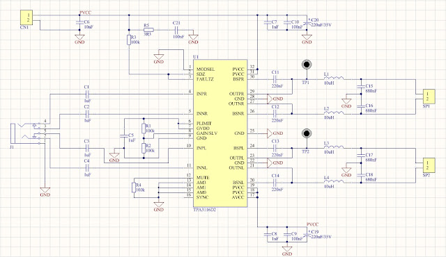 |
| Altium Designer Schematic |
Bill of Material
| N |
Designator |
Value |
Footprint |
Manufacturer |
Farnell |
| 1 |
C16, C17, C18, C19 |
220nF/50V |
0805 |
Kemet |
1288261 |
| 2 |
C26,C27,C28,C29 |
680nF/50V |
0805 |
Kemet |
1414702 |
| 3 |
C20,C23,C30,C31,C32,C33 |
1nF/50V |
0805 |
Kemet |
1414660 |
| 4 |
C57,C34,C37,C38,C40 |
10nF/50V |
0805 |
Kemet |
1414662 |
| 5 |
C21,C24,C58 |
100nF/50V |
0805 |
AVX |
1740673 |
| 6 |
C11,C12,C13,C14,C15 |
1uF/50V |
0805 |
Multicomp |
1759502 |
| 7 |
C22,C25 |
220uF/35V |
0805 |
Panasonic LOW ESR |
1219473 |
| 8 |
U1 |
TPA31162 |
TSSOP-32 |
Texas Instruments |
2144259 |
| 9 |
R10,R15,R16,R17,R18 |
3R3 |
0805 |
Multicomp |
2447656 |
| 10 |
R13, R11, R14 |
100k |
0805 |
Yageo |
9237879 |
| 11 |
R12 |
20k |
0805 |
Multicomp |
2074395 |
| 12 |
L1,L2,L3,L4 |
10uH |
|
Bourns |
2374152 |
 |
| Top Assembly Layer |
 |
| Bottom Assembly Layer |
 |
| Top Copper Layer |
 |
| Bottom Copper Layer |
 |
| 3D Top |
 |
| 3D Bottom |
 |
| How it looks when printed out |
 |
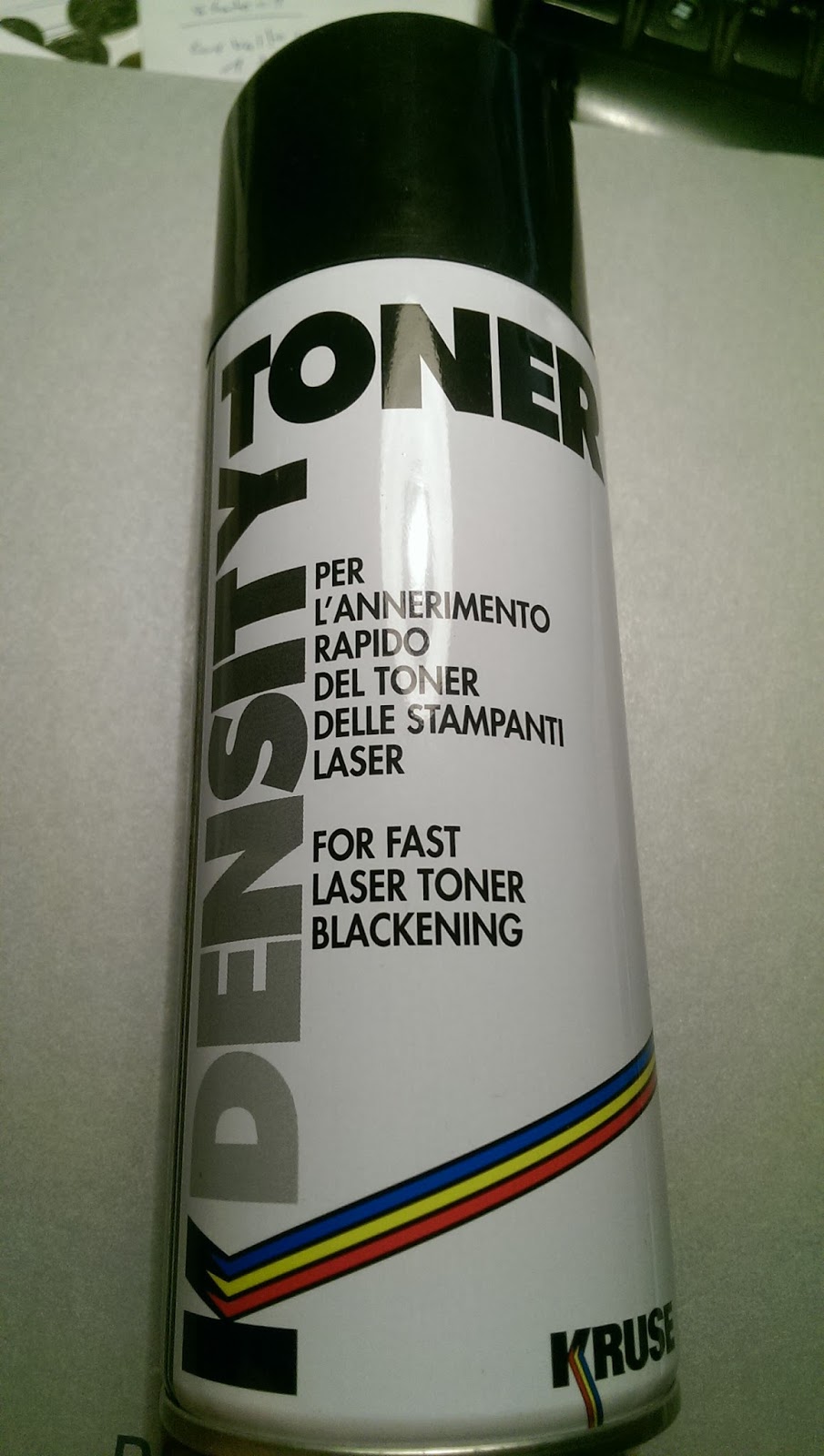
| Toner Density Spray |
Toner Density Spray is awesome for those who have old printers or printers with 600 DPI but also saves the thing if you don't want to print 2 pcs then glue it to fit perfectly.
Definitely RECOMMEND! Search in your store or on the internet.
Price is around 15-20$
 |
| This is my illuminator with broken VTF125 bulb |
 |
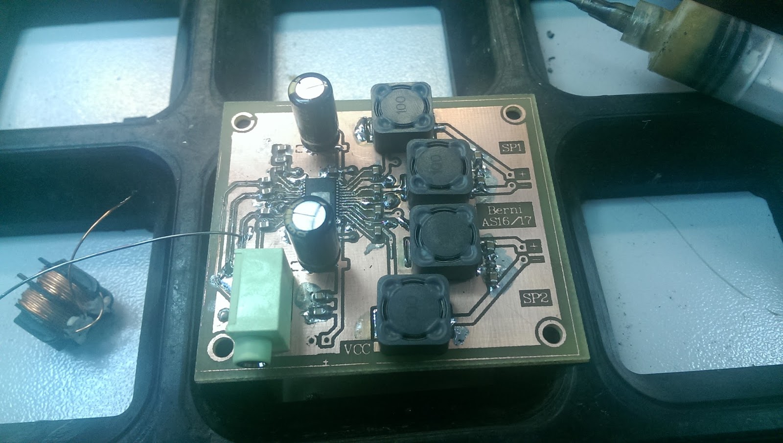
| Actual finished PCB |
 |
| Measurement setup |
THD measurements were conducted under this conditions:
- Supply Voltage U=12V
- Sine wave frequency f=1kHz
- Input Signal Amplitude Uin=0.5V
- Output Signal Amplitude Uout=1.5V
- U1, U3, U5 is 1.st, 3.rd , 5.th Harmonic
 |
| FFT - Fast Fourier Transformation |
U(Supply Voltage)
|
Input signal Amplitude(sine f=1kHz)
|
Uout
|
U1
|
U3
|
U5
|
12V
|
0.50V
|
1.5V
|
580mVrms
|
6.3mVrms
|
3.3mVrms
|
According to datasheet difference in THD is 22% .
Output Power, Efficiency is shown below:
|
Supply Voltage(U)
|
Supply Current(I)
|
Uin(sine, f=1kHz)
|
Rt (Load)
|
Up-p
Uout(peak-peak
|
P
|
Pout
|
h
|
|
12V
|
1.46A
|
1.3V
|
4Ω
|
10.6V
|
17.52W
|
14.04W
|
80.16%
|
According to datasheet
15W I measured in real environment
14.04W which is
0.96W or
6.8% less than manufacturer said. Which is quite good
You probably noticed the difference between Pout and P (all power) that's because of dissipated power which converts to heat on components with real impedance (parasitic resistance).
Dissipated power in my measurement can be calculated in 2 ways:
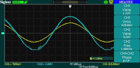
While I was doing my measurements I've also noticed that there are no maximum Amplitude of Input Signal in datasheet so I measured that as well.
Maximum Amplitude is a bit smaller than we can see Clipped signal on Oscilloscope
As we can see firstly there is cutting on the negative half-periode than positive half. That's happening due to low bias voltage.
|
Input Signal Amplitude
|
Clipping voltage
|
Half periode
|
|
1.3V
|
4.4V
|
Negative
|
|
1.5V
|
5.2V
|
Positive
|
 |
| First cutting negative half |
 |
| Cutting positive and negative |
 |
| Total cut off |
To summarize we can see that there are some deviations from official datasheet due to lack of mathematical analytic formulas we can't confirm our measurements nor design amplifier to meet our special requirements. That's not reason that this amplifier is not good enough to use for your boombox, speaker box, bluetooth, bigger audio systems (2.1) etc. on the contrary is Perfect due to price and easy to use.