As the title says it's one box which contains amplifier, speakers and LED :) I found that project when I was cleaning my room there was a watch box in that moment it seems like nice cleanly box and after some time i got amplifier and i started to combine these two. One afternoon i made sketch and said to myself that i must finish it, and that day i drill hole for input, output and also for turn ON/OFF and Volume Up/Down. That's how it started. Next day I experimented with Green LED and LM3915 because i wanted to made equalizer. That's it for now. After I'll explain what LM3915 do and some other stuff. :)
Let's see what do you need for it.
Parts:
1 - Empty Watch Box
1 - Amplifier 5-10W
1 - Prototype PCB 5x5cm (1,97x1,97 inch)
1 - 7.4V Battery
1 - LM3915
20 - LED 5mm (Color? - it's up to you)
1 - 3.7V Battery (for supplying lm3915)
2 - Switch button (1st for POWER ON/OFF, 2nd for inside or outside SPEAKER ON/OFF)
1 - Potentiometer
1 - Connector 3.5mm
1 - Male To Male 3.5mm Cable
2 - Speaker Terminal Connector
50cm of wire
+ About one free day :)
On this particular project there is no so much to explain. Everything has been already made and i just need to connect each other how i imagine! First i will show you how to connect lm3915
On the lm3915 datasheet you can find simple circuit how to connect it. There is not much philosophy with connecting just wire it like on the schematic but with one little EXCEPTION that is I'll use 3.7V instead 12-20V on PIN 3. Let's see how it looks like on schematic (theoretically) and practically
Let's see the amplifier, input, potentiometer
Amplifier
Input
Potentiometer
And finally the box
Now it's time for drilling hole and mounting :)
From left to right: 1st hole is for POWER ON/OFF and 2nd for SWITCHING speakers
Input
Inside box (input)
3rd one is POTENTIOMETER
Inside box
That's the terminal connectors for external speakers
I don't have anymore picture of the final product so when i get some time i will publish them too. Thanks for reading and looking :) If you like it please like, comment :)
This is the first of several tutorials about basic electronic. In this tutorial we will see symbols, uses and basics staff of DIODES. In the next tutorial known as "RectifierCircuits" we'll make and explain half-waverectifier, full-wave rectifier and filtering of Voltage after that transitors etc. :) Stay tuned.
There are several types of DIODES. I'll look for the most used diodes. So let's see the Symbols.
GENERIC DIODE
As her title says it's generic diode which can be made from silicon (Si) or germanium (Ge). The breakdown voltage of Silicon diode is 0.7V and for Germanium is about 0.3V.
TUNNEL DIODE Tunnel diode has breakdown voltage = 0V, in the forward direction has MAXIMUM (max) and MINIMUM (min) between these two acts as a negative-restistance element. What does it mean? That is when we increases voltage the Current will decreases. Because of that negative resistance it can be use for making high oscillations up to 20GHz also they can be used like faster switch.
PHOTO-DIODE
It's Germanium diode with dotted orsurfacePN junction. In the shut-off area presents resistance which value changes depends on intensity of light. This diode uses like faster light switch or indicator of brightness.
ZENER DIODE
In the breakdown area big changes of current doesn't occur almost no changes in voltage so it can uses for voltage stabilizer. Breakdown voltage is from 1.2V up to 150V. Zener diode connects vice versa in circuit, then Anode is on (-) and Chatode (+).
LED (Light-Emitting Diode) At least one time everyone see this diode it's well known LED (3mm, 5mm, 10mm) with all kind of color. What to say about it? Well, everyone knows how it looks like and a lot of you who will read this, is at least one time checked it with Higher voltage than nominal and if you hit the right + and - the diode is DEAD :) hahah but I have little advice for you how to determine where is anode and cathode. First if you have the new LED the LONGER LEG IS ANODE (+)and the shorter one is CATHODE (-). Next, a lot of times we don't have the new one and then we have to desolder from some PCB. Then you can't see the longer LEG but you can see inside LED and the smallest piece is ANODE (+)
VARICAP DIODE Capacity of the PN junction changes with changes of voltage. They made of Silicon or Galliumarsenide. They uses on the High frequency up to 20GHz. Also they are used as Capacitor for tuning resonant circuits and for automatic frequency regulator in TV/Radio devices.
That's it for these All About Diode #001 Tutorial :) Stay tuned :)
RGB LED i bought on ebay for i don't remember how much. It was very cheap and nice looking. I ordered and it comes for 2-3 weeks. I was impressed how well packed it was. I have to say that quality build is very high, i can't complain, and IR remote controller was very good.
After i tried it I realize that glows in beam/directed light. So if you have to lights up some particular part it's ok but if you want to use it for room lighting it's not very useful.
What about color? Well as RGB says (Red, Green, Blue) are the same, but some other colors like white, orange and variation on the same theme it's a bit messed up. Especially white, which is not white at all. There are also programs that loops. (Flash, Strobe, Smooth, Fade)
My homemade illuminator is about 25 years old, actually it's from my dad but he give it to me :). He made it in 1988-89 and till now it's still works well. I believe that will working another 25 years hahah. Design of the illuminator is really simple. For the UV bulb used mercury VTF 125W bulb without outside glass. If you creating one for yourself you have to carefully break or cut glass outside bulb(red on the picture). What is important for you to have untouched UV emitter (green on the picture). In addition you have to put silencer before connecting to city network or you will destroy the bulb. Construction is from iron, two bars, two screws and the shield(for directing UV Light)
LM7805 is voltage stabilizer, 7805 define what is output voltage in this case it's +5V. Otherwise there is a lot of voltage stabilizer like 7806, 7808, 7809, 7810, 7812, 7815etc. in each 78XX the last two digit define output voltage. I recommend that max input Voltage is not over 10V higher than nominal value in this case if we use lm7805 -->max input V is 15V. Can you put input over 15V? Yes, of course but then lm7805 will heating more and you have bigger dissipation. Let's see an example if you connect 20V on lm7805 with 2A that is P=15V*2A that is 30W which lm7805 must dissipate. So in order to avoid overheated you have to put bigger COOLER -->instantly bigger space, bigger device etc.
They could be in different package: TO-3, TO-220, SOT etc so when you creating schematic you should consider which one will you use.
How to connect LM7805
C3,C4 are here to reduce bumps of VOLTAGE it's usually about 100nF
**When it's about Power supplies it good practice to put diode before input because if you accidentally, forget the where is + and Switch polarity that + is on the - the diode is impermeable polarized and the circuit will never close and your Integrated circuit (IC) will be alive instead without diode if you switch polarity your circuit is done! It's easy to connect just Anode(+) must be on +12V
How it looks like with diode:
Here is datasheets for all lm78XX which i mentioned before.
Well, where to start. Ok, Let's start with Why I created Police light? First of all I really like police, fire and all kind of that light. I could watch it whole day. lol So I decided to make one for my personal use. One reason was because I like it, and second was it can help you when you stuck in traffic just turn on and everybody let you go. I was looking on internet for PIC or ATmega328, and I decided to use ATmega328 (Arduino) due to simplicity of writing code. PIC has more complicated process to program and upload code. I bought Arduino from some England seller on ebay. It was about 30 bucks. When it came for 2 weeks I started creating patterns with 4 LED-s on Breadboard with my own jumper wires. After I learned more and more I made one with 10 LED-s. With 10 LED I couldn't put it in CAR before I connected TRANSISTORS (for 12V) between Arduino and LED after i connected it I tried to put it in CAR but always one wire broke and I always need to solder it. That get irritated and I started think about to make PCB with ATmega328 and TRANSISTORS which can be easy to connect with LED. First I will show you my PROTOTYPE board and after that REVISION 1 where I changed TRANSISTORS MJE13005 with ULN2003A. How, Why, Where? I'll explain below!
Parts
1 - ATmega328P-PU - Microcontroller
2 - C1,C2 - 22pF - Capacitor (Come with Crystal)
2 - C3,C4 - 100nF - Capacitor ( Filter for power supply)
1 - D1 - 1N4003 - Diode
1 - MC7805T - Voltage stabilizer (From 12V to 5V for Microcontroller)
1 - JP1 - Header 2x20-pins (IDE cable in computers)
Here is Scheme of my prototype board.
I'll explain every segment of this scheme below.
1. Let's start with power supply As you can see on schematic, +12V and +5V is connected with Capacitor. Now someone will ask. Why do we need capacitor? Well, here is capacitors only used like filter of voltage, as we know that voltage isn't 100% smoothed. Capacitors must decrease bumps of voltage as much as possible then we can get smoothedvoltage which will be used for circuit. All circuit can work without these capacitors but if you can to put it into your schematic I deeply recommend. It's usually used 100nF capacitors for power supply. MC7805T is voltage stabilizer with 3 pin (Vin, GND, +5V) it's very easy to connect. I'll show you how to connect in Tutorial
2.ATmega328P-PU He contains all my programs (patterns) for light and with switch we can change them. What we need to be careful? When we creating Schematic with Microcontrollers, ALL +5V(pin 7 and 20) need to be connect together and also ALL GND(pin 8 and 22). And another thing is RESETpin MUST BE CONNECTED, you can do it like me or you can put one more switch button. How? I'll show you in tutorial.
3.RESET
Like I wrote above, RESET MUST BE CONNECTED. I don't know how it works in other Schematic/ PCB programs but if you didn't connect RESET PIN in ALTIUM DESIGNER. He won't make PCB before you connect RESET. My reset contains diode parallel with 10k resistor and all connected to +5V but also you can put switch button.
4. CRYSTAL with CAPACITORS and RESISTOR
Someone will ask why we need CRYSTAL, CAPACITORS and RESISTOR circuit can work without these components but ANSWER IS NO. Microcontroller CAN'T WORK WITHOUT THESE COMPONENTS. Why? Because without crystal processor(atmega328p-pu) is dead. Crystal with his own OSCILLATIONS creates frequency (tact,beat whatever) necessary for stable work of processor. If you don't have crystal your processor hasn't frequency for normal working and he won't work.
5. SWITCH BUTTON
Switch button is connected with 10k Resistor and he always hold state '0' when we press button, +5V make a little voltage drop on resistor and the rest voltage (3.6V-5V) go to ATmega328 which he reads like state '1' with changing states we change programms on LED. Can we put smaller resistance? Theoretically yes, but we want switch without errors. So if you put Smaller resistor, there will be bigger voltage drop and the rest of voltage (required 3.6V-5V for state '1') will be smaller and you risk mistake on ATmega328. If that voltage drop is in NEUTRAL border of 2.2V - 3.6V Atmega328 doesn't know which state it is. I usually use 10k Resistor. Here below is table of which state is which voltage. STATEVoltage '0' 0V - 2.2 V Neutral 2.2V - 3.6V '1' 3.6V - 5V
6. MJE13005, RESISTOR 4K7
Why we need MJE13005? This circuit is planed to put it in car like i wrote in introduction. I had 12V LED but Arduino or ATmega328 can give maximum of 5V with 5V LED can't work (flash) so i need transistor to connect 12V from car to LED without destroy microcontroller. How i connected MJE13005? Signal from ATmega is connected to BASE (1), EMITTER (3) to GND and COLLECTOR (2) goes to CATHODE(-) OF LED, 12V goes to ANODE(+) of LED. As you can see on Picture. What is GOOD TO KNOW ABOUT MJE13005? You need to know that if you are working with some fast patterns that loops 2 or more times in 10ms-20ms, MJE13005 is too slow for that fast switching he will do it 2 times but if you go to more and more loops he doesn't work properly. Also you can read all specs in MJE13005 DATASHEET.
7. HEADER 40X2 (Computer IDE cable)
It's an usual IDE cable which everybody have in computer (HDD to Motherboard). Why i used this header? I don't know, i had some motherboard on the desk and i thought that will be accessible to everybody who want to make one, also practically to connect and don't take so much space. Maybe someone don't understand why is there +12V, like i said +12V goes from car directly to Anode(+) of LED.
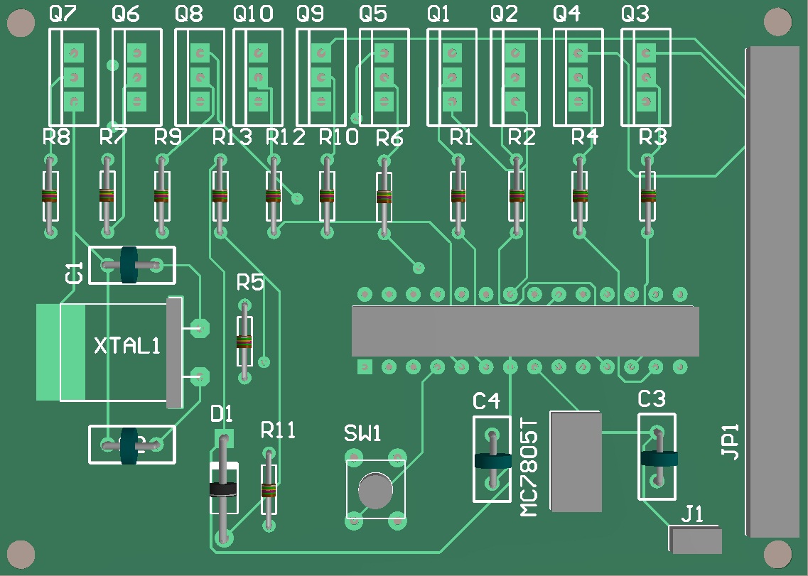
Here is Prototype board in Altium Designer 10
PROTOTYPE BOARD IN 3D
This is LED MODULE his feature is to facilitate connection between LED and MAIN BOARD.
Schematic
How it looks in Altium Designer 10
3D
REVISION 1 SCHEMATIC
Only difference between Prototype Board and REVISION 1 BOARD is that i changed transistors MJE13005 with ULN2003A. Why? Only reason was in speed, MJE13005 is too slow for fast patterns (10ms-20ms), ULN2003A satisfies all requirements for fast loops and that's why i changed it.
REVISION 1 In Altium Designer 10
Board in 3D
Also Everything above you can find in PDF file below, with Rules Check, Components and much more but if you want to make board from PDF file i must WARN you that everything in PDF isn't in 1:1 Proportion. Just send me Email or message and i will send you Altium File.
First is Prototype Board after Revision 1
I Hope that Will be helpful. If you don't understand something or something missing please Send Email or message. Please like, subscribe, comment. New project will be here soon.


