


Well, where to start. Ok, Let's start with Why I created Police light? First of all I really like police, fire and all kind of that light. I could watch it whole day. lol So I decided to make one for my personal use. One reason was because I like it, and second was it can help you when you stuck in traffic just turn on and everybody let you go. I was looking on internet for PIC or ATmega328, and I decided to use ATmega328 (Arduino) due to simplicity of writing code. PIC has more complicated process to program and upload code. I bought Arduino from some England seller on ebay. It was about 30 bucks. When it came for 2 weeks I started creating patterns with 4 LED-s on Breadboard with my own jumper wires. After I learned more and more I made one with 10 LED-s. With 10 LED I couldn't put it in CAR before I connected TRANSISTORS (for 12V) between Arduino and LED after i connected it I tried to put it in CAR but always one wire broke and I always need to solder it. That get irritated and I started think about to make PCB with ATmega328 and TRANSISTORS which can be easy to connect with LED. First I will show you my PROTOTYPE board and after that REVISION 1 where I changed TRANSISTORS MJE13005 with ULN2003A. How, Why, Where? I'll explain below!
Parts
Here is Scheme of my prototype board.
I'll explain every segment of this scheme below.

1. Let's start with power supply
As you can see on schematic, +12V and +5V is connected with Capacitor. Now someone will ask. Why do we need capacitor? Well, here is capacitors only used like filter of voltage, as we know that voltage isn't 100% smoothed. Capacitors must decrease bumps of voltage as much as possible then we can get smoothed voltage which will be used for circuit. All circuit can work without these capacitors but if you can to put it into your schematic I deeply recommend. It's usually used 100nF capacitors for power supply. MC7805T is voltage stabilizer with 3 pin (Vin, GND, +5V) it's very easy to connect. I'll show you how to connect in Tutorial

2. ATmega328P-PU
He contains all my programs (patterns) for light and with switch we can change them. What we need to be careful? When we creating Schematic with Microcontrollers, ALL +5V(pin 7 and 20) need to be connect together and also ALL GND(pin 8 and 22). And another thing is RESET pin MUST BE CONNECTED, you can do it like me or you can put one more switch button. How? I'll show you in tutorial.

3. RESET
Like I wrote above, RESET MUST BE CONNECTED. I don't know how it works in other Schematic/ PCB programs but if you didn't connect RESET PIN in ALTIUM DESIGNER. He won't make PCB before you connect RESET. My reset contains diode parallel with 10k resistor and all connected to +5V but also you can put switch button.
4. CRYSTAL with CAPACITORS and RESISTOR
Someone will ask why we need CRYSTAL, CAPACITORS and RESISTOR circuit can work without these components but ANSWER IS NO. Microcontroller CAN'T WORK WITHOUT THESE COMPONENTS. Why? Because without crystal processor(atmega328p-pu) is dead. Crystal with his own OSCILLATIONS creates frequency (tact,beat whatever) necessary for stable work of processor. If you don't have crystal your processor hasn't frequency for normal working and he won't work.

5. SWITCH BUTTON
Switch button is connected with 10k Resistor and he always hold state '0' when we press button, +5V make a little voltage drop on resistor and the rest voltage (3.6V-5V) go to ATmega328 which he reads like state '1' with changing states we change programms on LED. Can we put smaller resistance? Theoretically yes, but we want switch without errors. So if you put Smaller resistor, there will be bigger voltage drop and the rest of voltage (required 3.6V-5V for state '1') will be smaller and you risk mistake on ATmega328. If that voltage drop is in NEUTRAL border of 2.2V - 3.6V Atmega328 doesn't know which state it is. I usually use 10k Resistor. Here below is table of which state is which voltage.
STATE Voltage
'0' 0V - 2.2 V
Neutral 2.2V - 3.6V
'1' 3.6V - 5V

6. MJE13005, RESISTOR 4K7
Why we need MJE13005? This circuit is planed to put it in car like i wrote in introduction. I had 12V LED but Arduino or ATmega328 can give maximum of 5V with 5V LED can't work (flash) so i need transistor to connect 12V from car to LED without destroy microcontroller. How i connected MJE13005? Signal from ATmega is connected to BASE (1), EMITTER (3) to GND and COLLECTOR (2) goes to CATHODE(-) OF LED, 12V goes to ANODE(+) of LED. As you can see on Picture. What is GOOD TO KNOW ABOUT MJE13005? You need to know that if you are working with some fast patterns that loops 2 or more times in 10ms-20ms, MJE13005 is too slow for that fast switching he will do it 2 times but if you go to more and more loops he doesn't work properly. Also you can read all specs in MJE13005 DATASHEET.

7. HEADER 40X2 (Computer IDE cable)
It's an usual IDE cable which everybody have in computer (HDD to Motherboard). Why i used this header? I don't know, i had some motherboard on the desk and i thought that will be accessible to everybody who want to make one, also practically to connect and don't take so much space. Maybe someone don't understand why is there +12V, like i said +12V goes from car directly to Anode(+) of LED.

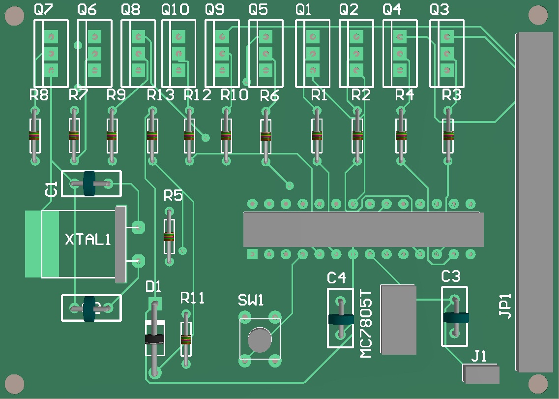
Here is Prototype board in Altium Designer 10


PROTOTYPE BOARD IN 3D
This is LED MODULE his feature is to facilitate connection between LED and MAIN BOARD.
Schematic

How it looks in Altium Designer 10
 3D
3D


REVISION 1 SCHEMATIC
Only difference between Prototype Board and REVISION 1 BOARD is that i changed transistors MJE13005 with ULN2003A. Why? Only reason was in speed, MJE13005 is too slow for fast patterns (10ms-20ms), ULN2003A satisfies all requirements for fast loops and that's why i changed it.
 REVISION 1 In Altium Designer 10


Board in 3D

Also Everything above you can find in PDF file below, with Rules Check, Components and much more but if you want to make board from PDF file i must WARN you that everything in PDF isn't in 1:1 Proportion. Just send me Email or message and i will send you Altium File.
First is Prototype Board after Revision 1
Police LED Light bar Prototype Board.pdf
Police LED Light bar REVISION 1. pdf
The Famous CODE for this Project.
Police LED Light Bar - Code
And The Results Is HERE
I Hope that Will be helpful. If you don't understand something or something missing please Send Email or message. Please like, subscribe, comment. New project will be here soon.
Parts
- 1 - ATmega328P-PU - Microcontroller
- 2 - C1,C2 - 22pF - Capacitor (Come with Crystal)
- 2 - C3,C4 - 100nF - Capacitor ( Filter for power supply)
- 1 - D1 - 1N4003 - Diode
- 1 - MC7805T - Voltage stabilizer (From 12V to 5V for Microcontroller)
- 2 - R1,R2 - 10kOhm - Resistor
- 1 - R3 - 1MOhm - Resistor (come parallel with Crystal)
- 2 - U1,U2 - ULN2003A - Transistors
- 1 - XTAL1 - Crystal (quartz) oscillator
- 1 - SW1 - Switch button (For changing patterns)
- 1 - J1 - Header 2-pin for power supply
- 1 - JP1 - Header 2x20-pins (IDE cable in computers)
Here is Scheme of my prototype board.
I'll explain every segment of this scheme below.
1. Let's start with power supply
As you can see on schematic, +12V and +5V is connected with Capacitor. Now someone will ask. Why do we need capacitor? Well, here is capacitors only used like filter of voltage, as we know that voltage isn't 100% smoothed. Capacitors must decrease bumps of voltage as much as possible then we can get smoothed voltage which will be used for circuit. All circuit can work without these capacitors but if you can to put it into your schematic I deeply recommend. It's usually used 100nF capacitors for power supply. MC7805T is voltage stabilizer with 3 pin (Vin, GND, +5V) it's very easy to connect. I'll show you how to connect in Tutorial
2. ATmega328P-PU
He contains all my programs (patterns) for light and with switch we can change them. What we need to be careful? When we creating Schematic with Microcontrollers, ALL +5V(pin 7 and 20) need to be connect together and also ALL GND(pin 8 and 22). And another thing is RESET pin MUST BE CONNECTED, you can do it like me or you can put one more switch button. How? I'll show you in tutorial.
3. RESET
Like I wrote above, RESET MUST BE CONNECTED. I don't know how it works in other Schematic/ PCB programs but if you didn't connect RESET PIN in ALTIUM DESIGNER. He won't make PCB before you connect RESET. My reset contains diode parallel with 10k resistor and all connected to +5V but also you can put switch button.
4. CRYSTAL with CAPACITORS and RESISTOR
Someone will ask why we need CRYSTAL, CAPACITORS and RESISTOR circuit can work without these components but ANSWER IS NO. Microcontroller CAN'T WORK WITHOUT THESE COMPONENTS. Why? Because without crystal processor(atmega328p-pu) is dead. Crystal with his own OSCILLATIONS creates frequency (tact,beat whatever) necessary for stable work of processor. If you don't have crystal your processor hasn't frequency for normal working and he won't work.
5. SWITCH BUTTON
Switch button is connected with 10k Resistor and he always hold state '0' when we press button, +5V make a little voltage drop on resistor and the rest voltage (3.6V-5V) go to ATmega328 which he reads like state '1' with changing states we change programms on LED. Can we put smaller resistance? Theoretically yes, but we want switch without errors. So if you put Smaller resistor, there will be bigger voltage drop and the rest of voltage (required 3.6V-5V for state '1') will be smaller and you risk mistake on ATmega328. If that voltage drop is in NEUTRAL border of 2.2V - 3.6V Atmega328 doesn't know which state it is. I usually use 10k Resistor. Here below is table of which state is which voltage.
STATE Voltage
'0' 0V - 2.2 V
Neutral 2.2V - 3.6V
'1' 3.6V - 5V
6. MJE13005, RESISTOR 4K7
Why we need MJE13005? This circuit is planed to put it in car like i wrote in introduction. I had 12V LED but Arduino or ATmega328 can give maximum of 5V with 5V LED can't work (flash) so i need transistor to connect 12V from car to LED without destroy microcontroller. How i connected MJE13005? Signal from ATmega is connected to BASE (1), EMITTER (3) to GND and COLLECTOR (2) goes to CATHODE(-) OF LED, 12V goes to ANODE(+) of LED. As you can see on Picture. What is GOOD TO KNOW ABOUT MJE13005? You need to know that if you are working with some fast patterns that loops 2 or more times in 10ms-20ms, MJE13005 is too slow for that fast switching he will do it 2 times but if you go to more and more loops he doesn't work properly. Also you can read all specs in MJE13005 DATASHEET.

7. HEADER 40X2 (Computer IDE cable)
It's an usual IDE cable which everybody have in computer (HDD to Motherboard). Why i used this header? I don't know, i had some motherboard on the desk and i thought that will be accessible to everybody who want to make one, also practically to connect and don't take so much space. Maybe someone don't understand why is there +12V, like i said +12V goes from car directly to Anode(+) of LED.
Here is Prototype board in Altium Designer 10

PROTOTYPE BOARD IN 3D
This is LED MODULE his feature is to facilitate connection between LED and MAIN BOARD.
Schematic
How it looks in Altium Designer 10
REVISION 1 SCHEMATIC
Only difference between Prototype Board and REVISION 1 BOARD is that i changed transistors MJE13005 with ULN2003A. Why? Only reason was in speed, MJE13005 is too slow for fast patterns (10ms-20ms), ULN2003A satisfies all requirements for fast loops and that's why i changed it.
Board in 3D
Also Everything above you can find in PDF file below, with Rules Check, Components and much more but if you want to make board from PDF file i must WARN you that everything in PDF isn't in 1:1 Proportion. Just send me Email or message and i will send you Altium File.
First is Prototype Board after Revision 1
Police LED Light bar Prototype Board.pdf
Police LED Light bar REVISION 1. pdf
The Famous CODE for this Project.
Police LED Light Bar - Code
And The Results Is HERE
I Hope that Will be helpful. If you don't understand something or something missing please Send Email or message. Please like, subscribe, comment. New project will be here soon.


